LOADING...
Control I/O function blocks · Factory I/O simulation
Object assembly automation
I used Control I/O function blocks to make a Factory I/O assembly scene work: feeding parts, coordinating clamps, transferring a lid onto a base and requesting the next parts.
This work connects my machinery and fault-finding background with PLC logic and automation engineering. The focus is on describing a process as states, conditions and transitions, then using the simulated machine to see the result.
Sequence controlBoolean logicTimers & edge triggersState latches
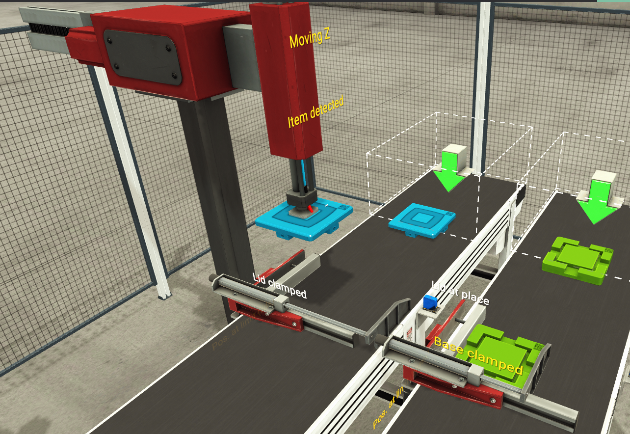
Feed and position
Separate conveyors bring the lid and base to the assembly positions. The scene exposes clamp and position signals for the sequence.
Select the image to inspect it at full size ↗See the assembly cycle
Video edit pending
Running-cycle footage recorded
A short edited demonstration will be added here. For now, the scene captures and control logic below document the work.
From positioned parts to an assembly
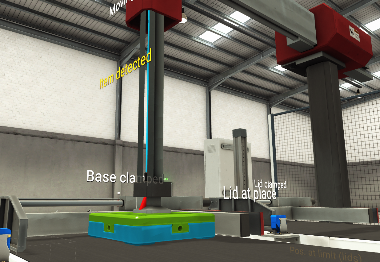
Bring the parts together
The assembly capture shows the two parts together beneath the transfer mechanism, alongside the scene’s detection and clamp labels.
Select the image to inspect it at full size ↗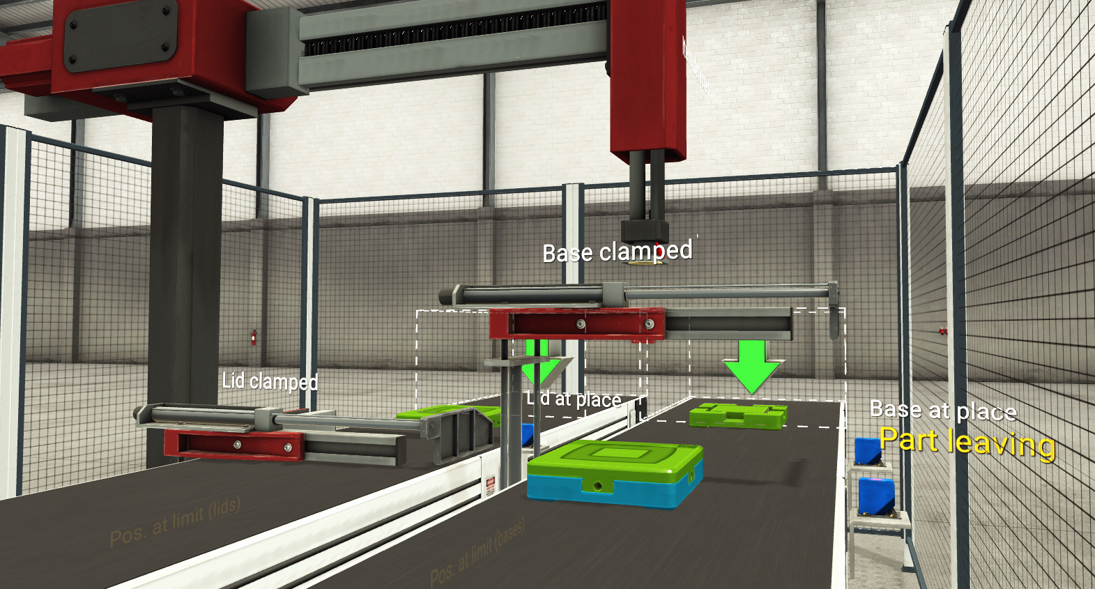
Discharge the assembly
The completed assembly is shown at the “Part leaving” sensor, with further parts visible on the incoming conveyors.
Select the image to inspect it at full size ↗Inside the control sequence
These Control I/O screenshots show the networks behind the scene. Each caption describes the visible signals and blocks; full-size images keep the connections and labels available for closer inspection.
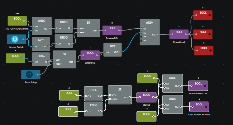
Operating state and mode selection
Master-switch and simulation-running inputs feed a latched Powered On state. An ESTOPPED latch and reset input feed the Operational condition; Started is used with mode inputs to derive Manual Mode ON and Auto Process Running.
Select the image to inspect it at full size ↗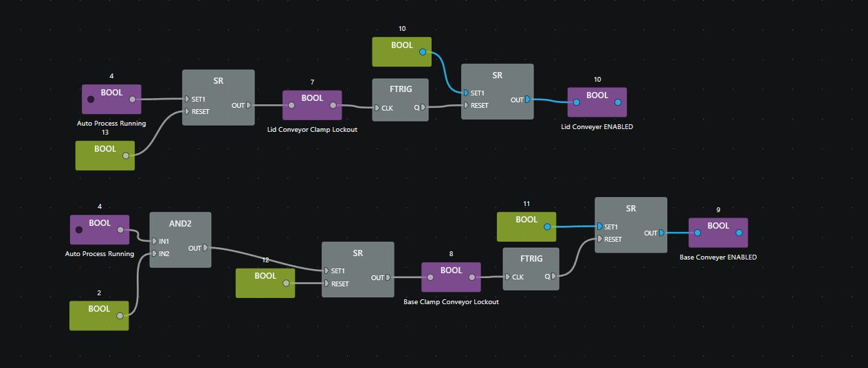
Conveyor enable and clamp lockout
Separate lid and base networks use stored states and falling-edge triggers to coordinate conveyor enables with clamp lockouts.
Select the image to inspect it at full size ↗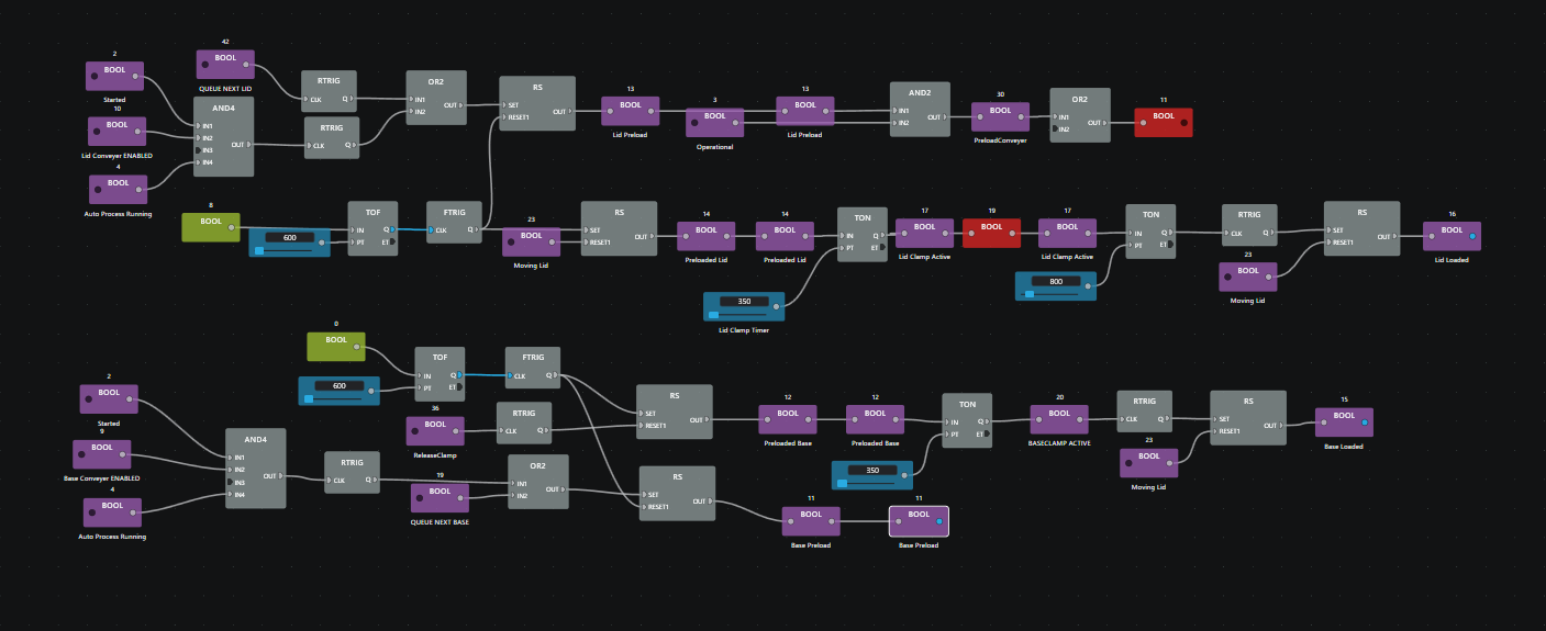
Loading and timed clamping
Parallel lid and base paths combine start and next-part requests with conveyor enables. TON and TOF timers, edge triggers and RS latches represent preload, clamp activation and loaded states.
Select the image to inspect it at full size ↗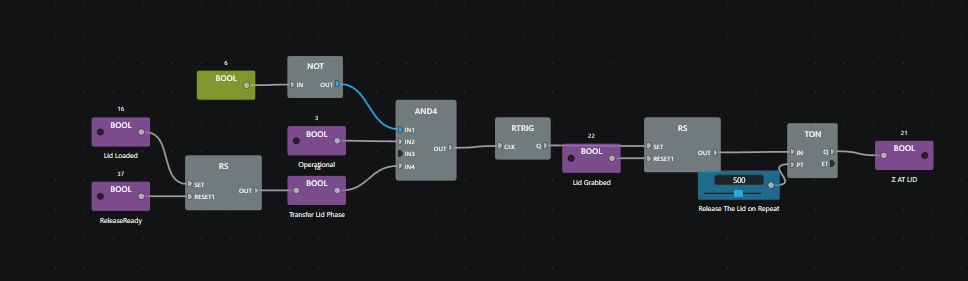
Lid pickup phase
Lid Loaded, Operational and Transfer Lid Phase participate in the pickup network. A TON block feeds the Z AT LID state.
Select the image to inspect it at full size ↗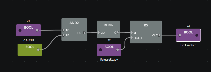
Remember the pickup state
The Z AT LID condition and a further Boolean input feed a rising-edge trigger and an RS latch named Lid Grabbed. ReleaseReady provides the reset.
Select the image to inspect it at full size ↗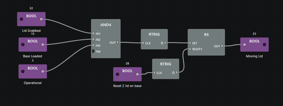
Gate the transfer
Lid Grabbed, Base Loaded and Operational feed the Moving Lid network. The movement state is latched, with a separate reset path labelled Reset Z lid on base.
Select the image to inspect it at full size ↗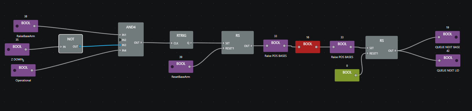
Request the next parts
The base-arm network combines RaiseBaseArm, an inverted Z DOWN signal and Operational. Its latched output feeds QUEUE NEXT BASE and QUEUE NEXT LID requests.
Select the image to inspect it at full size ↗What this work demonstrates
Practical function-block programming, explicit process states, timed actions, sensor-dependent transitions and coordination between material handling and assembly. These are concrete steps toward PLC and automation engineering and consultancy, building on hands-on industrial experience.
The current record covers a working simulation and screenshots of its control logic. Physical PLC deployment, repeated-cycle reliability and fault-recovery testing are not established by these captures. The simulated stop/reset network is application logic, not evidence of a validated machine-safety system.
Next evidence to add
- A short edited running-cycle video showing feed, assembly, discharge and the next cycle.
- A saved control project and I/O map to make the sequence reproducible.
- Documented repeat-cycle, stop/reset and interrupted-cycle checks, with outcomes and changes.